Bolt-through appliance foot maker
Printable replacement feet that bolt through onto a threaded boss, self-checked
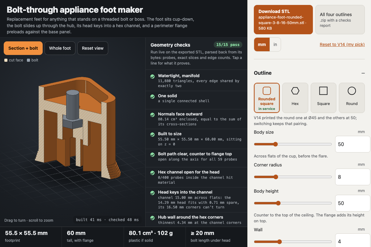
Screenshot of the tool as it opens; it is a real capture, not a mockup.
Thanks, your report was sent.
Report a problem or a newer version
What it makes
A binary STL (mm) of a bolt-through replacement foot: a hollow cup with a flared base, a hub with a hex channel that holds the bolt head, ribs clipped to the inner wall, a solid ceiling the head pulls on, and a perimeter-only flange that seats on the base panel while its open centre clears the threaded boss. It is a browser port of a parts-as-code design whose V14 rounded-square foot is in service on an espresso machine after physical fit tests from V10 to V14; at the V14 settings the four outlines match that project's Python build in bounding box and volume. A zip option exports all four outlines with a text report of every check.
How to use it
- Take one old foot off. Note the thread and measure the bolt head across flats, then pick the matching thread preset (3/8"-16 is the V14 default) or type your own sizes.
- Measure how far the threaded boss sticks out below the base panel and set it under Ceiling & flange; the flange has to be taller.
- Choose an outline (rounded square, hex, square or round) and a body size that covers the old footprint; adjust the hub, ribs, ceiling and flange if you need to.
- Read the Geometry checks panel. Every line should pass; tap a line to see what it proves.
- Download the STL and print it cup-opening down, as modelled, with no supports. PETG is the tested material.
- Drop the bolt in from below so its head sits in the hex channel, then spin the whole foot onto the boss until the flange ring bears on the panel. Snug, not cranked.
Build notes
- The checks run on the exported file itself, parsed back from its bytes: edge-manifold and single-shell tests, a volume cross-check against the section areas, containment probes along the bolt axis, in the hex channel, ceiling, flange and between the ribs, and exact section slices that measure the channel across flats and the shaft hole.
- The V14 ceiling was recorded as 4 mm in one file and 8 mm in the session notes; 8 is used. Check an in-service foot with calipers before reprinting.
- The flange replaces any riser or spacer that used to sit on the bolt, so it won't work with those accessories.
- Head sizes follow ASME B18.2.1 and ISO 4017; DIN 933 M10 heads are 17 mm across flats, so measure yours.
- Works fully offline; nothing is fetched.